HP Procurve Network Hardware Configuration Guide, Part One
Contents:
1. General Switch Information
2. Software Update HOWTO
3. VLAN Information & CIDR Subnet Mask Notation
4. VLAN Configuration – HP 5308 XL Switches
5. VLAN Configuration – HP 2650 Switches
General Switch Information
As part of a complete redeisgn of the company network I have had to setup and deploy two HP 5308xl core-switches and 10 2650 48 port edge-switches.
The aims of the project were simple:
- Increase manageability of network resources.
- Division of the network into VLAN’s.
- Provide fault tolerance in the event of a core switch failure.
- Increase security of network resources.
- Increase speed / data throughput.
In my first article for the site I thought I would share my experiences of setting up this hardware, and provide a refernce so that if you’re planning to upgrade your network at least you can find some in-depth information on these products and how to configure them.
This article covers the setup of RSTP, XRRP, Routing, VLANS, ACL’s and TRUNKS on these switches, and tries to shed light on what exactly each of these functions has to offer for your network.
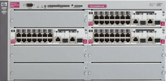
Firstly the switches themselves. We recieved two HP5308xl J4819A 8 module core switches:

We have 5 low-contention xl Mini-GBIC Modules (J4878B), each with 4 hot-swap connectors (these can be 1000T / 1000SX / 1000LX / 1000 LH connectors) and 3 ProCurve Switch xl 16-port 10/100/1000 Modules (J4907A) (as shown in the picture above) installed in both of our 5308xl’s.
Also in the shipment were 10 2650 J4899A edge-switches:

The switches came with all the usual attire; serial cables for console based configuration, AC power cable, and documentation on CD, note, there was no printed documentation with the 2650 switches, and the 5308xl’s came with a quick setup guide, all other documentation in on the CD’s that are in the pack. This was as expected though as the complete manual for the products is well over 500 pages!
First of all I’d like to take a look at the 5308xl switches, these will be at the very core of our network and thus are mission critical. They need to be feature rich and fast.
Device Specifications for 5308xl Switch as supplied by HP:
Part
|
Specification
|
Ports
|
8 open module slots.
Supports a maximum of 192 10/100 ports or 128 Gigabit ports.
|
Physical Characteristics
– Dimensions
– Weight
|
15.3 x 17.4 x 8.75 in. (38.86 x 44.2 x 22.23 cm) 5U height
26.65 lb (11.99 kg) fully loaded
|
Memory And Processor
– Fabric module:
– Flash ROM’s:
– Packet Buffer Size:
|
Motorola PowerPC @ 200 MHz 12 MB flash 32 MB SDRAM
Dual Flash
36MB
|
Performance
– Latency
– Throughput
– Switch Fabric Speed
– Routing Table Size
|
<6 µs (FIFO)
up to 48 million pps
76.8 Gbps
10000 entries |
Environment
– Operating Temperature:
– Operating Relative Humidity:
– Non-Operating/Storage
Temperature:
– Non-Operating/Storage
Relative Humidty:
– Altitude:
|
32 °F to 104 °F (0 °C to 40 °C)
15 % to 95 % at 104 °F (40 °C), noncondensing
-40 °F to 158 °F (-40 °C to 70 °C)
15 % to 95 % at 149 °F (65 °C), noncondensing
Up to 15091 ft (4.6 km) |
Electrical Characteristics
– Maximum BTUs:
– Voltage:
– Current:
– Power:
– Frequency:
|
2152 BTU/hr
100-127 VAC/200-240 VAC
8.2 A /3.8 A
630 W
50/60 Hz |
There is an incredible list of features and protocols that the 5308xl switches support, making them exteremly good value for money, and an excellent choice for your network.
- Layer 3 IP routing
- Router redundancy protocol XRRP
- OSPF-ECMP
- IP multicast routing (PIM dense)
- IP multicast (data-driven IGMPv3)
- Virus throttling
- ICMP Throttleing
- Mesh configuration
- 802.1s Multiple Spanning Tree
- 802.1w RSTP
- VLAN support and tagging
- 802.3ad LACP
- Access control lists (ACLs)
- Identity-driven per-port ACL
- Multiple authentication methods:
IEEE 802.1X
Web-based
MAC address based
- Authentication flexibility:
Multiple 802.1X users per port
Concurrent 802.1X Authentication
- Traffic prioritization (802.1p)
|
- 802.1v protocol VLANs
- GVRP
- Port security
- MAC address lockout
- Source port filtering
- TACACS+
- Secure Shell (SSHv2)
- Secure Sockets Layer (SSL)
- Secure FTP
- Switch management logon security
- Layer 4 prioritization
- Bandwidth shaping:
Rate limiting
Guaranteed minimums
- RMON, XRMON, sFlow, and SMON
- UDP helper function (IP Helper)
- Link Layer Discovery Protocol (LLDP)
- LLDP-MED (Media Endpoint Discovery)
- Friendly port names
- ProCurve/IEEE Auto-MDIX
- Hot-swappable modules
- Dual flash images
|
All in all not a bad setup at all! A theoretical maximum of 76.8Gb/sec is quick, certainly a lot faster than what we had in place previously.
I also like the ‘xl modules’ as they provide a great deal of flexibility for network infastructure. The 5308xl can house up to 8 XL modules, the 5304xl can house up to 4. The modules come in several different flavours, providing Power Over Ethernet, Hot-Swap Mini-GBIC Modules for 1000SX / 1000T / 1000LX / 1000LH and even an Access Control Module, for more details on XL modules see the links below:
ProCurve Switch xl Access Controller Module (J8162A)
ProCurve Switch xl 10/100-TX PoE Module (J8161A )
ProCurve Switch xl 16-port 10/100/1000 Module (J4907A)
ProCurve Switch xl Mini-GBIC Module (J4878B)
ProCurve Switch xl 100-FX MTRJ Module (J4852A)
ProCurve Switch xl 100/1000-T Module (J4821B)
ProCurve Switch xl 10/100-TX Module (J4820B)
Now I’ll take a look at the features of our edge-switches, the 2650 switches.
Device specifications for 2650 switch as suppiled by HP:
Part
|
Specification
|
| Ports
|
48 RJ-45 10/100 ports
(IEEE 802.3 Type 10Base-T, IEEE 802.3u Type 100Base-T)
1 RS-232C DB-9 console port
2 Dual Personality Ports
each port can be used as either an RJ-45 10/100/1000 port
(IEEE 802.3 Type 10Base-T; 802.3u Type 100Base-TX;
802.3ab 1000Base-T Gigabit Ethernet) or an open mini-GBIC
slot (for use with mini-GBIC transceivers)
|
Physical Characteristics
– Dimensions
– Weight
|
12.8 x 17.32 x 1.75 in. (32.51 x 43.99 x 4.45 cm) 1U height
9.78 lb (4.4 kg) fully loaded
|
Memory And Processor
– Processor:
– Flash Capacity:
– SDRAM:
|
Motorola PowerPC MPC8245, 266 MHz
32MB
36MB
|
Performance
– Latency
– Throughput
– Switch Fabric Speed
– Routing Table Size
|
< 13.3 µs (LIFO)(FIFO)
up to 10.1 million pps
13.6 Gbps
8000 entries |
Environment
– Operating Temperature:
– Operating Relative Humidity:
– Non-Operating/Storage
Temperature:
– Non-Operating/Storage
Relative Humidty:
– Altitude:
|
32 °F to 131 °F (0 °C to 55 °C)
15 % to 95 % at 104 °F (40 °C), noncondensing
-40 °F to 158 °F (-40 °C to 70 °C)
15 % to 95 % at 149 °F (65 °C), noncondensing
Up to 15091 ft (4.6 km) |
Electrical Characteristics
– Maximum BTUs:
– Voltage:
– Current:
– Power:
– Frequency:
|
341 BTU/hr
100-120 VAC/200-240 VAC
1.5A
100 W
50/60 Hz |
The flexibility provided by the dual-personality ports is very useful; we have made use of this feature in our network with 2 of these switches having fitted 1000SX Gbic modules to these ports. This versatility means that these switches can go into virtually any pre-setup enviroment. The modules couldn’t be any simpler to fit, and can be done when the switch is on or off: Simply take off the dust cover and slide the module into place firmly. The light on the port will change from ‘T’ to ‘M.’ Examples of these modules can be seen below:

There’s a long list of features for an edge-switch, making them excellent vlaue for money, and a sound investment for your network.
- 13.6 Gbps Backplane
- Dual-personality ports; 100/1000T/LX/LH/SX
- Basic IP routing
- IP multicast (IGMPv3 snooping)
- 802.3ad LACP
- Remote Monitoring
- 802.1X and RADIUS network login
- TACACS+:
- Secure Shell (SSHv2)
- Secure Sockets Layer (SSL)
- VLAN support and tagging
- Group VLAN Registration Protocol (GVRP)
- 802.1w RSTP
- 802.1s Multiple Spanning Tree
- VLAN support and tagging
- Group VLAN Registration Protocol (GVRP)
- VLAN support and tagging
|
- Group VLAN Registration Protocol (GVRP)
- 802.1w RSTP
- 802.1s Multiple Spanning Tree
- ProCurve/IEEE Auto-MDIX
- Friendly port names
- Dual flash images
- Source port filtering
- Web-based authenticationv
- MAC address lockout
- Secure FTP
- Port security
- IP Lockdown
- Layer 4 prioritization
- Class of Service (CoS)
- Traffic prioritization (802.1p)
- Troubleshooting
- Stacking capability
|
Now you’re a least fairly familiar with the switches and what they can do, so we’ll start to configure them…
Contents:
1. General Switch Information
2. Software Update HOWTO
3. VLAN Information & CIDR Subnet Mask Notation
4. VLAN Configuration – HP 5308 XL Switches
5. VLAN Configuration – HP 2650 Switches
Software Update HOWTO.
The first job was to check that all software was up-to-date on the switches. The 5308xl’s weren’t up to date, and neither were the 2650’s. A few things you’ll need if you have to do this, we’ll start with the 5308xl first.
We need to check that the BOOT ROM on your switch is recent enough to take the software update, it needs to be version 5.04 or newer for the current software release 10.04.
To check your BOOT ROM version you’ll need to connect your switch to your PC / Laptop with a serial cable and turn the switch on. Next you’ll need to load HyperTerminal, (under Start>Programs>Accessories>Communications) select the COM port you attached the camble to and the proceed to setup a new connection called ‘HP,’ you’ll be using this a lot so be sure to save it. Connection settings are as follows:
Bits per sec: 9600
Data bits: 8
Parity: None
Stop bits: 1
Flow control: None

Once this is done press enter twice and you should see the HP welcome screen:
HP J4819A ProCurve Switch 5308xl
Firmware revision E.10.04
Copyright (C) 1991-2005 Hewlett-Packard Co. All Rights Reserved.
RESTRICTED RIGHTS LEGEND
Use, duplication, or disclosure by the Government is subject to restrictions
as set forth in subdivision (b) (3) (ii) of the Rights in Technical Data and
Computer Software clause at 52.227-7013.
HEWLETT-PACKARD COMPANY, 3000 Hanover St., Palo Alto, CA 94303
We’d like to keep you up to date about:
* Software feature updates
* New product announcements
* Special events
Please register your products now at: www.ProCurve.com
Press any key to continue
Press Enter, then type ‘sh system-information‘ – this will disply current switch and software version information. You’re looking for ROM Version, and Firmware Version. ROM Version is your BOOT ROM, if it’s 5.04 you’re good to update to software version 10.04.
If its not you’ll need to update your software to version 7.40 first as this version includes the BOOT ROM upgrade. Then you’ll be able to upgrade to version 10.04. Check what the most recent version is on the HP site!
The next thing you want to do is set an temporary IP up so you can update the software. If you type the command ‘config‘ then hit enter you’ll be in admin mode for the switch.
Type ‘vlan 1‘ and hit enter. Then type ‘IP address 10.0.0.1/24‘ and hit enter again. The switch now has a temprorary IP which we can use to upload the new software. If you then type ‘untag A1‘ this will enable you to connect a computer to port A1 in the same IP range (ie 10.0.0.2/24) and communicate with the switch.
The command ‘untag‘ makes the port that you untag a part of the vlan in which you run the command; so if you type vlan 2, and then untag B1, port B1 becomes part of vlan 2. Any machine you connect to the untagged port must be in the same IP range as the vlan IP address you set. The switch can have one IP per vlan.
I will discuss VLAN’s shortly, so don’t worry about what they are if you don’t know.
The next thing you’ll need is a TFTP (Trivial File Transfer Protocol) server, which will enable you to upload files to or from the switch from a computer.
Click Here to download Solar Winds TFTP server (external site will load in another window.)
When this has been downloaded install the application. Connect your computer up to the switch in the port you ‘untagged’ and set the IP address to 10.0.0.2, subnet to 255.255.255.0 (/24) and set the gateway as 10.0.0.1. Don’t worry about DNS settings Once this is done you should be able to ping the switch.
Now load the SolarWinds TFTP server application. Click on file on the menu, and go to configure. Select the security tab and then click the ‘Transmit and Recieve Files‘ option. Your TFTP server is ready to go.

You’ll find in the root of your system drive (normally c:\\) there is a new folder called TFTP-Root. Extract the contents of the zip files downloaded from this site and place the files into this folder. You’ll now be able to transfer them to the switch.
Go back to the hyperterminal window you have open and ping the IP address of your machine from the switch. So long as this is successful, which it should be, you’ll be able to transfer files. Note: If your BOOT ROM is not version 5.04 you should install sowftare version 7.40 first, and then 10.04.
Type ‘copy tftp flash 10.0.0.2 E_10_04.swi‘ the press ‘y’ to continue, and enter. 10.0.0.2 is the IP address of the machine running the TFTP server software, E_10_04.swi is the name of the file on the server. When this processes has finished you’ll need to reboot the switch. Type ‘boot and ‘y’ to continue.
When the unit comes back up, you’ll have to press ‘Enter’ twice to bring up the main screen again, and then, to check the update worked, enter the command ‘show system-information‘ your firmware version should read 10.04 (or 7.40 if you’ve upgraded your BOOT ROM first, if so, now you should repaet the process with the 10.04 software.)
Now we move on to the configuration of the switch, click here for the next page.
Contents:
1. General Switch Information
2. Software Update HOWTO
3. VLAN Information & CIDR Subnet Mask Notation
4. VLAN Configuration – HP 5308 XL Switches
5. VLAN Configuration – HP 2650 Switches
VLAN information and VLAN Information & CIDR Subnet Mask Notation
What is a VLAN?
Virtual LAN’s (VLAN) are a means for you to break down your network into smaller manageable chunks. Each VLAN is an independent broadcast domain defined within a set of switches, even though they all connect into the same switch. This is very useful in larger network enviroments, where network useage has reached around 200 or more nodes. At this level network speed will decrease, unless the load on the network is reduced. This is where VLAN’s come in.

The image above depicts a simple VLAN setup. Using the hardware reviewed in this article all machines in the network can communicate, despite the fact they are in seperate broadcast domains. This is explained later on this page.
How you divide your network is down to you. You can seperate it by physical location, ie Ground Floor, First Floor etc., by department, application or by building. They key to deploying a successful VLAN infastructure is that you don’t over-complicate things. If there are 5 departments on one floor, but only 50 machines, there is simply no point in making 5 VLAN’s, you may as well have just a single VLAN. This makes managing the network easier, and configuration of the switches easier too. Remeber simplicity is key, this way other members of the IT team will understand your setup.
The network infastructure I deployed was divided by physical location, and the by device type. I deployed 6 VLANS:
- VLAN100: Server VLAN
- VLAN132: Apple Macintosh VLAN
- VLAN133: Downstairs M2
- VLAN134: Upstairs M2
- VLAN135: IT Management VLAN
- VLAN136: M1
I placed the apple nodes in a seperate VLAN due to their useage of appletalk protocol. This protocol is a broadcast protocol, which, in large quantities can hinder network performance for all devices. By seperating the apple nodes into a seperate VLAN the broadcast packets are restricted to that VLAN alone. Broadcast packets are NOT routed by the switches to other VLAN’s.
M1 and M2 are seperate buildings linked by fibre pairs. The distance between them is roughly 250 Meters. The number of machines in the M1 building is fewer than 50, therefore I have created a single VLAN, despite there being several departments. This single VLAN has plenty of scope to accomodate any future growth of the IT infastructure in this building.
VLAN Names / Numbers
The switches refer to each VLAN by a number or name. It is important that from the number you can make the link as to what the VLAN is in place for. My VLAN’s are named 100, 132, 133, 134, 135 and 136 because of the IP range they cover:
- VLAN 100: Covers IP range 10.0.0.0 – 10.0.31.0 (IP Range starts with 10.0 – hence 100)
- VLAN132: Covers IP Range 10.0.32.0 – 10.0.32.254 (IP Range starts 10.0.32 – hence 132)
- VLAN133: Covers IP Range 10.0.33.0 – 10.0.33.254 (IP Range starts 10.0.33 – hence 133)
- VLAN134: Covers IP Range 10.0.34.0 – 10.0.34.254 (IP Range starts 10.0.34 – hence 134)
- VLAN135: Covers IP Range 10.0.35.0 – 10.0.35.254 (IP Range starts 10.0.35 – hence 135)
- VLAN136: Covers IP Range 10.0.36.0 – 10.0.36.254 (IP Range starts 10.0.36 – hence 136)
Using this naming structure I can easily make the connection to the IP range from the VLAN number. I suggest you use a similar naming routine, but keep your numbers below 1000.
Types of VLAN available on the 5308xl and 2650 switches
In the case of these switches there are three type of VLAN that can be deployed:
- Port Based – individual ports on switches are assigned to VLAN’s.
- MAC Address Based – Nodes are granted VLAN membership based upon MAC address.
- Protocol Based – This is however limited to a few select protocols.
This guide will cover the setup of port based VLAN’s.
Why setup VLAN’s?
Simple:
- VLAN’s allow Network administrator to control traffic flow and reduce uneccesary broadcast traffic.
- VLAN’s allow for nodes to be moved with ease as indiciudal ports on switches, therefore nodes, can be assigned to VLAN’s.
- VLAN’s allow for increased security as access between them can be limited through Access Control Lists.
It is easy to see why VLAN’s are now industry standard in large network infastructures, the level of control and security over resources attainable is unlike any flat network.
At this point you should have an idea as to how you’re going to divide your network up. If this is not the case, work this out before continuing. VLAN’s are reffered to by number in the switches. You should have an idea as to what you’re going to call each of the VLANS.
VLAN Inter-Communication
As mentioned above, it is possible for machines or devices in one VLAN to communicate with machines or devices in another, as long as there is a router in place. The switches discussed in this article include IP Routing features that enable VLANS to communicate with one another. With IP Routing disabled VLAN’s are treuly seperate networks, no traffic will pass between them. With IP routing turned on machines on one VLAN will communicate with machines on another as if they were on the same network. The setup of IP Routing is discussed in the 5308xl VLAN configuration guide.
CIDR Subnet Mask Notation
Before we continue to configure the units I would reccomend you familiarise yourself with CIDR subnet mask notation. No doubt you are familiar with subnets being written as ‘255.255.255.0’ or similar, however this is not the standard used in the networking industry. A mask of 255.255.255.0 can be written as ‘/24’ in CIDR notation. Why? Well this is becuase an IP address is made up of four octets, or four groups of eight bits. In a 255.255.255.0 mask, 24 bits are set to ‘1’. In a 255.0.0.0 only 8 bits are set to one, thus /8 represents a 255.0.0.0 mask.
CIDR notation is very simple, the table below explains how the CIDR notation works, and what it represents. If you’re still lost I reccomend you look up ‘bits,’IP addresses and subnet masks on google!
| Subnet Mask |
CIDR Prefix |
Total IP’s |
Usable IP’s |
Number of Class C networks |
| 255.255.255.255 |
/32 |
1 |
1 |
1/256th |
| 255.255.255.254 |
/31 |
2 |
0 |
1/128th |
| 255.255.255.252 |
/30 |
4 |
2 |
1/64th |
| 255.255.255.248 |
/29 |
8 |
6 |
1/32nd |
| 255.255.255.240 |
/28 |
16 |
14 |
1/16th |
| 255.255.255.224 |
/27 |
32 |
30 |
1/8th |
| 255.255.255.192 |
/26 |
64 |
62 |
1/4th |
| 255.255.255.128 |
/25 |
128 |
126 |
1 half |
| 255.255.255.0 |
/24 |
256 |
254 |
1 |
| 255.255.254.0 |
/23 |
512 |
510 |
2 |
| 255.255.252.0 |
/22 |
1024 |
1022 |
4 |
| 255.255.248.0 |
/21 |
2048 |
2046 |
8 |
| 255.255.240.0 |
/20 |
4096 |
4094 |
16 |
| 255.255.224.0 |
/19 |
8192 |
8190 |
32 |
| 255.255.192.0 |
/18 |
16,384 |
16,382 |
64 |
| 255.255.128.0 |
/17 |
32,768 |
32,766 |
128 |
| 255.255.0.0 |
/16 |
65,536 |
65,534 |
256 |
| 255.254.0.0 |
/15 |
131,072 |
131,070 |
512 |
| 255.252.0.0 |
/14 |
262,144 |
262,142 |
1024 |
| 255.248.0.0 |
/13 |
524,288 |
524,286 |
2048 |
| 255.240.0.0 |
/12 |
1,048,576 |
1,048,574 |
4096 |
| 255.224.0.0 |
/11 |
2,097,152 |
2,097,150 |
8192 |
| 255.192.0.0 |
/10 |
4,194,304 |
4,194,302 |
16,384 |
| 255.128.0.0 |
/9 |
8,388,608 |
8,388,606 |
32,768 |
| 255.0.0.0 |
/8 |
16,777,216 |
16,777,214 |
65,536 |
| 254.0.0.0 |
/7 |
33,554,432 |
33,554,430 |
131,072 |
| 252.0.0.0 |
/6 |
67,108,864 |
67,108,862 |
262,144 |
| 248.0.0.0 |
/5 |
134,217,728 |
134,217,726 |
1,048,576 |
| 240.0.0.0 |
/4 |
268,435,456 |
268,435,454 |
2,097,152 |
| 224.0.0.0 |
/3 |
536,870,912 |
536,870,910 |
4,194,304 |
| 192.0.0.0 |
/2 |
1,073,741,824 |
1,073,741,822 |
8,388,608 |
| 128.0.0.0 |
/1 |
2,147,483,648 |
2,147,483,646 |
16,777,216 |
| 0.0.0.0 |
/0 |
4,294,967,296 |
4,294,967,294 |
33,554,432 |
The table is provided for refernce, you may wish to print it for future reference for when we come to setup our VLAN’s on the switches.
With that said we can now move on to configuring the 5308XL switches.
Contents:
1. General Switch Information
2. Software Update HOWTO
3. VLAN Information & CIDR Subnet Mask Notation
4. VLAN Configuration – HP 5308 XL Switches
5. VLAN Configuration – HP 2650 Switches
VLAN Configuration – HP5308xl Switches
Use this section to configure the 5308xl switches ONLY.
An important note: VLAN 1, or the default VLAN should not be used for anything at all. All ports you use should be assigned to a VLAN which you have created.The only ports which remain a member of this VLAN are TRUNKS, which will be discussed later on in this article.
You can configure VLAN’s on these switches through both the command line interface (CLI), or by the web-interface. Throughout this guide I will focus on using the CLI. This interface offers more control, and access to several features unavailable in the web-interface. I tend to think of the web-interface as a monitoring-tool rather than a configuration utility.
You’ll need your serial cable again, hook it up and start the hyperterminal connection as discussed here.
Ensure that the only cables connected at this time are the power cables and serial cable. No network cables should be attached to the switches at this point.
Once in, enter the command ‘config‘
The, to check that no current IP addresses are assign to any of the VLAN in the switch we’ll erase the startup-config. Type the command ‘erase startup config‘ agree to the reboot and wait until the switch comes back on-line.
Once the switch has come back on-line and you’re in the CLI, enter the ‘config‘ command.
To setup a new VLAN from this point simply enter the command ‘VLAN XXX‘ where ‘XXX’ is the number for your VLAN. Lets say we’ve used the command ‘VLAN 100.’ You will then enter the context menu for this VLAN, and will be able to set an IP address for this VLAN as well as configure many other features such as XRRP which are covered later on in this guide. This context menu is donated by ‘(vlan-100)’ after the name of the switch, as shown in the image below:
Having setup VLAN 100 we’ll assign an IP address to it and then make some of the ports on the switch members of this VLAN.
To assign an IP address use the command ‘ip address x.x.x.x /x‘
For VLAN100, if I wanted to assign the IP address 10.0.2.1 /24 I would use the command ‘ip address 10.0.2.1 /24‘
Not familiar with the terminology ‘/24’ then have a look at the table below, this should shed some light on the matter. This is a way of writing the subnet mask, referred to as CIDR Subnet Mask Notation. The ’24’ means 24 bits used in the subnet, 24 is equivalent to ‘255.255.255.0’. You can also use a standard subnet mask (i.e 255.255.255.0 after the IP address, the command would look like this ‘ip address 10.0.2.1 255.255.255.0.
Lets set another VLAN. Firstly we need to come out of the context menu for VLAN100. Type ‘exit‘ and hit enter. This will take you back into the ‘config‘ menu.
From here type the comand ‘VLAN‘ followed by the number of the next VLAN you want to setup. I will use ‘VLAN 132.’ Once this command is enetered you will again enter the context menu for this VLAN, denoted by (vlan-132) after the name of the switch. Through this you can once again set an IP address for this VLAN. Obviously this must be within the IP range you have selected, I would reccomend using the first or last IP in the range. So for my VLAN, I enetered the command ip address 10.0.32.1 /24.’
Hopefully by this point you’ll get the idea, do the same for all the other VLAN’s you want to setup, then we need to look at the second 5308xl. When you think you’re done you can check what VLAN’s are configured on the switch and which IP’s are assigned to the switch by using the commands ‘show vlans‘ and ‘show ip.’
Show VLAN’s will produce the following information on screen:
Show IP will produce the following output:

From the above we can determin that I have sucessfully setup all VLAN’s on the switch and assigned the correct IP addresses and subnet masks.
The configuration process for the second switch is identicle, however ensure that the IP address you set for the VLAN’s is different from the address set in the first switch. For example, in setting up VLAN132 in my configuration I would use the settings: 10.0.32.1/24 for switch one, then 10.0.32.2/24 for switch 2. For VLAN133 I would use 10.0.33.1/24 for switch one and 10.0.33.2/24 for switch two and so on…
IP Routing Setup
This is the simplist part of this setup, simply type the command ‘ip routing.’ This will turn on routing between VLAN’s. Without this machines on VLAN 100 wouldn’t be able to see machines on VLAN132 or VLAN133, or any of the other VLAN’s. This is becuase VLAN’s are seperate subnets, or independent networks. Routing needs to take place in order for two or more VLAN’s to inter-communicate. Both the 5308xl and 2650 switches are capable of IP routing. However, we will only turn IP routing ‘on’ on the 5308xl switches.
Naming your switch
One final note, it’s worth naming the switches at this stage so that when you are connected to them it is obvious which one you are configuring. In order to do this type config and press enter, then type hostname followed by the name which you intend to give the switch, then hit enter. For example:
hostname HP5308XLSwitch1
Now we can move on to configuring the HP 2650 Switches to ensure they are compatible with the VLAN configuartion we have setup on the 5308xl units. Click here to continue.
Contents:
1. General Switch Information
2. Software Update HOWTO
3. VLAN Information & CIDR Subnet Mask Notation
4. VLAN Configuration – HP 5308 XL Switches
5. VLAN Configuration – HP 2650 Switches
VLAN Configuration – HP 2650 Switches
VLAN configuration on the 2650 units is much the same as before with the 5308xl Switches, but with a few important differences.
IP routing is not enabled on the switches. All traffic is sent back to the switch for routing. The reason for this is that the 5308xl core switch is far more effective at routing these packets, as you’ll have seen from the specifiactions on the first page of this article.
Each switch has only a single IP address on your management VLAN. So in the case of our network all of the 2650 units have an IP address on VLAN135 but no IP addresses on any other VLAN. This ensures security of the switch configuration as end-users outside of VLAN135 are literally unaware of the 2650 units as they cannot ping or gain access to the switches on their set IP addresses.
VLAN’s are setup as before, by enetring the switches configuration context menu. But rather than declare an IP for all VLAN’s we simply enter the command ‘VLAN XXX’ where XXX is the number for your VLAN and then enter the next ‘VLAN XXX’ command until all VLAN’s have been assigned.
For example, to setup VLAN100 and 132 on a 2650 switch I would enter the commands:
config
VLAN100
VLAN132
That is all that is needed. For VLAN 135 in my network I would enter the command:
config
VLAN 135
ip address 10.0.35.X /24
This is because VLAN 135 is the management VLAN, and all 2650 units have a single IP address on this VLAN only.
The end product as seen with show vlans:

And with show ip:
Having configured the switches for basic VLAN networking we now move on to the more technical confguration of these units.
Part Two (Now in-line)
Contents:
1. VLAN Membership, Linking Switches and Trunks
2. XL Router Redundancy Protocol (XRRP) Configuration
3. Rapid Spanning-Tree Protocol (RSTP) Configuration
4. Access Control List (ACL) configuration
Firstly welcome back to the second part of this guide. This part of this guide explores the more technical features of these units and explains what benifits they offer for your network aswell as how to confgure them step by step.
1. VLAN Membership, Linking Switches and Trunks VLAN Membership
Machine VLAN membership can be based upon one three different factors as discussed in the previous chapter:
(i) port based
(ii) MAC address based
(iii) protocol based.
In this capter I will focus upon port based membership; as this type of VLAN is extremely easy to setup. I will use the command line throughout this section to configure the VLAN’s onboth the 2650 and 5308xl switches, although it is possible to use the web interface. We have already setup our VLAN’s on the switches, now we need to assign ports to them. Until this is done all ports are by default a member of VLAN1, the ‘default VLAN’, which means our VLAN’s will not function.
When making a port a member of a particular VLAN we can use one of two commands; ‘tag‘ or ‘untag.‘ These commands are executed under the context menu for the VLAN you wish to add the port to.Explanations of these commands are below:
- ‘Untag‘: An ‘untagged’ port is a member of the VLAN to which it is untagged. A port can only be ‘untagged’ on a single VLAN, but can be ‘tagged’ on several VLAN’s. This is the command used for edge-ports (ports your machines / servers plug into.)
- ‘Tag‘: Tagged ports are primariliy used to make trunks or links between switches. They are also used with servers and workstations that have VLAN aware network cards. ‘Tagged’ ports are discussed further down this page.
Adding ports to a VLAN
Once a port has become a member, or has been ‘untagged‘ in a particluar VLAN any device you plug into this port is automatically a member of this same VLAN. So if I make port ‘G1’ on my switch a member of ‘VLAN 100,’ and then I plug a server into this port, the server will then be a part of VLAN 100. If its IP is not DHCP it will need to be configured so that it is an IP compatible with this VLAN – in the caseof VLAN 100, 10.0.0.0 / 24.
This also applies if I plug in a non-VLAN aware switch. Every port on the switch would be a part of the VLANthat the switch has its uplink cable plugged into.
The commands below illustrate how to untag ports g1-g4 to make them part of VLAN 100:
config
vlan 100
untag g1-g4
write mem
You can untag multiple ports by simply using a hyphen; ie ‘ untag G1-G14‘. This commandwould untag all foutrteen ports.
And if you want to configure multiple modules in your 5308xl’s you can use a comma to seperate groups; ie ‘untag A1-A4, B1-B4, C1-C4‘. You can also use this to group sets of numbered ports, ie ‘untag 1-4, 8-12, 16-20‘.This should make port configuration on your edge-switches, and core switches very simple and quick. If departments move, rather than change patch cables round you can simply re-assign patch cables to different VLAN’s in the switch configuration.
I used the 16 port XL modules (J4907A) in the 5308xl switches for direct connectivity of servers. Therefore all the ports in thesemodules were ‘untagged‘ to VLAN 100 – my server VLAN. This is simple to remember, and requires no configuration at a later dateif another server is plugged into a vacant port. This is very simple for others in you department to understand. Remember simplicity is key.
For the 2650 edge-switches configuration varied depending on location.
Once you’re done you can check that you have configured your ports correctly by using the command ‘show vlan xxx‘ where ‘xxx’ is the VLAN number you want to check the port configurationfor. This command will produce a similar output as illustrated in the image below:
Linking Switches
This can be done one of two ways. You can use trunks, groups of multiple ports acting as a single, high-speed connection between switches,or you can use a single 1000T (or equivalent) uplink port. Your selection will vary depending on the speed and redundancy requirements of your network. Either method requires VLAN’s to be ‘tagged‘ on the uplink port / trunk. If you opt for the higher bandwith option you can skip this section and go to the heading ‘Trunk Information and Configuration.’ There are further considerations to take into account if you chose the high-bandwidth route which are discussed below.
I opted for the single-port gigabit-link between the edge-switches and core-switches. There are actually two uplink cables for the 2650 units:one going to the primary 5308xl switch one, the other to the secondary. However the secondary link is setup as failover only; all traffic is blocked accross this cable, unless the primary link fails. This was done using ‘spanning-tree‘ which is discussed here.
Why have I done this? Well I wanted a completely redundant system. By having one switch do all the work, if it fails the second switch can easily take overall switching duties. The second point to consider is that there is little point in having a slow link accross the two 5308xl switches. Even if you were to setup an 8Gb link it is still 70gb/sec slower!
Therefore I opted for a single switch enviroment, with the second switch as backup. A single HP 5308xl switch is more than fast enough for most networks.
As a reliable failover-link I created a four port trunk between the two 5308xl units. This link is trunked with multiple cablesso that if xrrp (discussed here.) is enablesthe switches will not failover in the event of a cable being taken out by mistake. Trunks are discuessed in detail after this section.
I used the four port XL modules (J4878B) in the 5308xl switches for uplink cables to the 2650 edge-switches, and to create the trunk between the two 5308switches. These have a lower contention ratio in comparison to the 16 port modules, meaning they are more effective as uplink ports.These modules are in slots A, B, C, D and E on both units.
With this in mind the setup for my system looks like this:
config
trunk A1-A4 trk1
vlan 100
tag trk1, B1-B4, C1-C4, D1-D4, E1-E4
vlan 132
tag trk1, B1-B4, C1-C4, D1-D4, E1-E4
vlan 133
tag trk1, B1-B4, C1-C4, D1-D4, E1-E4
vlan 134
tag trk1, B1-B4, C1-C4, D1-D4, E1-E4
vlan 135
tag trk1, B1-B4, C1-C4, D1-D4, E1-E4
vlan 136
tag trk1, B1-B4, C1-C4, D1-D4, E1-E4
write mem
Both of the 5308xl switches were configured in the same manor. This meant that any of these ports could be used as an uplink to the 2650 switches, or any spare ports could be used in the future for further expansion of the network infastructure.
The essential thing to remember when setting up any link between switches is that the ports in the switches at the both ends are setupexactly the same:
Image © HP – Taken From Advanced Traffic Management Guide
As you can see in the above image, Switch ‘1’ has port X and port Y configured with VLAN 1 untagged and VLAN 132 tagged. Switch ‘2’ has port A and port Bconfigured in exactly the same manor. It does not matter that they are different ports, just that they are setup with thesame VLAN configuration. Therefore you would need to ‘tag’ the VLAN’s in the same fashion on the 2650 switches as you did on the 5308xl switches.
NOTE: At this point only one uplink cable should be connected to your 2650 units. If both are connected before spanning-tree is configured and enabled a network loop will exist and the switches will fail to respond.
Trunk Information and Configuration
A Trunk is a group of ‘tagged‘ ports used in linking switches together.You can use up to 8 ports in a single trunk with the 5308xl switches, and up to 4 ports on the 2650 switches. These ‘trunked’ ports will act as a single, high speed connection, thus increasing available bandwidth substantially. This is particlullay useful when linking your edge-switches to your core-switches, or if you have to link core-switches together.
It is important to note cross-switch bandwidth restrictions at this point. The 5308xl units have an internal bandwidth of up to 76.8Gb/sec,it is not possible for us to create a link that is as fast as this between two of them. The fastest ‘trunk’ we can create is 8 Gb/sec.Therefore when you plan your network you must ensure that servers are placed on the same core-switch as the client devices that will be usingthem. There would be little point in plugging a server into one of the 5308xl switches and having the edge-switch that serves all of the client devicesconnected up to the second 5308xl unit. This would create a bottle-neck in between the switches. If you plan your network properly there will be littleneed for cross core-switch traffic, thus eliminating any bottle-necks.
When creating a VLAN trunk, ports need not be sequential. What this means is you can use ports G1, G4 and H16 to create a single trunk,you don’t have to use G1-G3. This is illustrated in the image below:
Image © HP – Taken From Advanced Traffic Management Guide
VLAN aware hardware adds an VLAN ID to each packet sent, this ID will be the number you use for your VLAN’s. By tagging ports on VLAN’s you allow the tagged VLAN’s to send traffic accross the port, the only way this can be identified from other VLAN traffic is this VLAN ID. Note that a trunk connecting two switchesmust have the same VLAN ‘tagging’ configuration on both switches in order for the trunk to work.
VLAN traffic can also be spread accross different trunks. For instance you could create trunk1 (trk1) and set it up so that traffic from VLAN 100,132 and 133 only travel across it. You could then setup trunk2 (trk2) and set it up so that traffic from VLAN 134, 135 and 136 only travel accross it. There is great scope for flexibilty with trunks.
For instance, if you know a particular VLAN needs a high-bandwidth link between switches then you could potentially create up to a 8 Gb/sec link for that individual VLAN. Whilst all the other, slower VLAN’s could travel across a 1 Gb/sec link
I used a single trunk in my design to link the two 5308xl units. This link was a failover link, all VLAN’s were tagged on this trunk. The commands below illustrate how to create a trunk and tag VLAN’s to it:
config
trunk A1-A4 trk1
vlan 100
tag trk1
vlan 132
tag trk1
vlan 133
tag trk1
vlan 134
tag trk1
vlan 135
tag trk1
vlan 136
tag trk1
write mem
This would create a trunk named ‘trk1’ consisting of ports A1-A4. All VLAN’s are tagged on this trunk. I would configure both 5308xl siwtchesin the same way. After doing so, 4 cables can be connected from ports A1-A4 on switch 1 to A1-A4 on switch 2 without causing any looping problems.
The commands I used to configure the switches in my network for this section are as follows:
HP 5308xl Primary:
config
trunk A1-A4 trk1
vlan 100
untag G1-G16, H1-H16
tag trk1, B1-B4, C1-C4, D1-D4, E1-E4
vlan 132
tag trk1, B1-B4, C1-C4, D1-D4, E1-E4
vlan 133
tag trk1, B1-B4, C1-C4, D1-D4, E1-E4
vlan 134
tag trk1, B1-B4, C1-C4, D1-D4, E1-E4
vlan 135
tag trk1, B1-B4, C1-C4, D1-D4, E1-E4
vlan 136
tag trk1, B1-B4, C1-C4, D1-D4, E1-E4
write mem
|
|
HP 5308xl Secondary:
config
trunk A1-A4 trk1
vlan 100
untag G1-G16, H1-H16
tag trk1, B1-B4, C1-C4, D1-D4, E1-E4
vlan 132
tag trk1, B1-B4, C1-C4, D1-D4, E1-E4
vlan 133
tag trk1, B1-B4, C1-C4, D1-D4, E1-E4
vlan 134
tag trk1, B1-B4, C1-C4, D1-D4, E1-E4
vlan 135
tag trk1, B1-B4, C1-C4, D1-D4, E1-E4
vlan 136
tag trk1, B1-B4, C1-C4, D1-D4, E1-E4
write mem
|
|
HP 2650 Switches:
vlan 100
tag 49-50
vlan 132
tag 49-50
vlan 133
tag 49-50
vlan 134
tag 49-50
vlan 135
tag 49-50
vlan 136
tag 49-50
|
Having configured the switches for VLAN’s its not time to setup XRRP, or XL Router Redundancy Protocol in order to providerouting failover in the event of a core-switch failure.
Contents:
1. VLAN Membership, Linking Switches and Trunks
2. XL Router Redundancy Protocol (XRRP) Configuration
3. Rapid Spanning-Tree Protocol (RSTP) Configuration
4. Access Control List (ACL) configuration
XL Redundant Routing Protocol (XRRP) Overview & Configuration XRRP Overview
XRRP, or XL Router Redundancy Protocol allows for failover in the event of a router failing and is similar in function to Cisco’s VRRP. It is worth noting at this point that the 2650 units do not support XRRP. This section of the configuration is for the 5308xl units only.
Pairs of switches are configured to behave as backup routers for one-another, each pair is referred to as a “Protection Domain.” If a router fails in a Protection Domain the other router takes over all routing duties of the failed router. Most importantly, the transfer of these duties is transparent to end users.
Each switch in a \”Protection Domain\” functions as a \”Virtual Router\” interface. A Virtual Interface exists for each router on every VLAN. If a switch fails, the remaining switch uses these Virtual Router interfaces to take control of the routing duties for the failed switch.
A protection domain is monitored using \”Advertisement Intervals\” – a time interval at which XRRP packets are sent out on each virtual router interface. These packets are used to confirm that the switch is functioning correctly. If a switch in a Protection Domain fails to receive the Advertisement packets from its paired switch it will take over the routing duties until the Advertisement packets are detected again.
Certain perquisites exists in order for XRRP to function correctly:
Both routers must have identical network access; they must have access to the same VLAN subnets and client nodes without having to pass through each other.
A good example of this configuration is illustrated below:
Image © HP Advanced Traffic Management Guide
As you can see each switch has access to the servers and layer 2 switch independently. This means that XRRP will function correctly, because in the event of a switch failure the remaining switch has access to all areas of the network.
XRRP Configuration
Before we begin, let me recap on my current setup.I have 6 VLAN’s;
VLAN 100 – IP Range 10.0.0.0/19
VLAN 132 – IP Range 10.0.32.0/24
VLAN 133 – IP Range 10.0.33.0/24
VLAN 134 – IP Range 10.0.34.0/24
VLAN 135 – IP Range 10.0.35.0/24
VLAN 136 – IP Range 10.0.36.0/24
5308xl Switch One is configured with the following IP addresses:
VLAN 100 – 10.0.2.1/19
VLAN 132 – 10.0.32.1/24
VLAN 133 – 10.0.33.1/24
VLAN 134 – 10.0.33.1/24
VLAN 135 – 10.0.33.1/24
VLAN 136 – 10.0.33.1/24
5308xl Switch Two is configured with the following IP addresses:
VLAN 100 – 10.0.2.2/19
VLAN 132 – 10.0.32.2/24
VLAN 133 – 10.0.33.2/24
VLAN 134 – 10.0.33.2/24
VLAN 135 – 10.0.33.2/24
VLAN 136 – 10.0.33.2/24
All of the 2650 Units have an IP address on VLAN 135 ONLY. This is for the sole purpose of management and configuration. These range from 10.0.35.3 to 10.0.35.12. It is not necessary however for these switches to have any IP address, but without an IP remote management is not possible.
Configuration of XRRP on the 5308xl units is quite simple. As our network consists of only two 5308xl Core Switches I will create only a single XRRP Protection Domain. I have bi-cabled all of our servers, a cable runs form each of the 5308xl units into dual-port, giga-bit network cards on each server. Each edge-switch has been cabled so that it has a direct link to both core-switches. In both cases, the second link is not always active and is controlled by Spanning Tree Protocol, which is discussed in depth later on in this article.
I have configured 6 VLAN’s on these switches, and I will ensure that XRRP is configured to server each of these in the event of a switch / router failure.
We’ll start with the primary switch; start a telnet session with this switch. Next, enter the “config” command.
Firstly we create the XRRP protection domain using the command “XRRP Domain 1“
Now we establish this switch as the first, or primary, router in the protection domain, using the command “XRRP Router 1“
For each VLAN we must establish a physical router and a virtual router interface. The primary router interface will be the current switch address, the virtual router address will be the address of the secondary switch so that the primary switch can identify which packets need to be routed in the event of the second switch failing, or vice versa.
Lets begin with VLAN 100.
First we establish the physical, primary, router interface; “XRRP instance 1 100” The “1” indicates that it is the primary instance. “100” represents the VLAN number to which this XRRP rule is to be applied.
Now we must establish the virtual router interface; “XRRP instance 2 100 IP 10.0.2.2/19.” The “2” indicates that it is the secondary, or virtual, interface. \”100\” represents the VLAN number to which the rule is applied to. “IP 10.0.2.2/19” represents the second core-switch IP address on VLAN 100.
With that done, the configuration for VLAN 100 on 5308xl Switch One is complete. Now, the same steps must be completed for the remaining five VLANS on this switch. The commands to complete this configuration are listed below:
XRRP instance 1 132
XRRP instance 2 132 IP 10.0.32.2/24
XRRP instance 1 133 XRRP instance 2 133 IP 10.0.33.2/24
XRRP instance 1 134XRRP instance 2 134 IP 10.0.34.2/24
XRRP instance 1 135XRRP instance 2 135 IP 10.0.35.2/24
XRRP instance 1 136XRRP instance 2 136 IP 10.0.36.2/24
This completes the XRRP Configuration on 5308xl Switch One.
Lets move on to configuring the secondary 5308xl switch in our XRRP Protection Domain.
First, establish a telnet session with the second switch and enter the “config” command.
Now we declare this switch a member of the same XRRP Protection Domain as the first switch; “XRRP domain 1.”
Next we need to declare this router as the second router in the protection domain; “XRRP Router 2.”
We can now configure the XRRP Rules on this unit. The primary switch we be the first instance on all VLAN’s, this switch will be the secondary instance.
XRRP instance 1 100 IP 10.0.2.1/19XRRP instance 2 100
XRRP instance 1 132 IP 10.0.32.1/24XRRP instance 2 132
XRRP instance 1 133 IP 10.0.33.1/24XRRP instance 2 133
XRRP instance 1 134 IP 10.0.34.1/24XRRP instance 2 134
XRRP instance 1 135 IP 10.0.35.1/24XRRP instance 2 135
XRRP instance 1 136 IP 10.0.36.1/24XRRP instance 2 136
With this configured we are now ready to test that XRRP failover is working!
XRRP Testing
The simplest way to check whether XRRP is working at this stage is as follows. First, ensure both 5308xl units are connected and switched on. Next, connect a client workstation to the primary 5308xl unit. Ensure the client TCP/IP gateway address is set as the IP of the second 5308xl switch on the VLAN to which the port it is connected to is assigned. For testing purposes my client workstation is connected to VLAN 100 with an IP of 10.0.2.3. Its gateway is set as 10.0.2.2.
Contents:
1. VLAN Membership, Linking Switches and Trunks
2. XL Router Redundancy Protocol (XRRP) Configuration
3. Rapid Spanning-Tree Protocol (RSTP) Configuration
4. Access Control List (ACL) configuration
Rapid Reconfiguration Spanning Tree Protocol (RSTP) Configuration Howto
What is Rapid Reconfiguration Spanning Tree Protocol?
Spanning Tree Protocol is a means of maintaining redundant loops or connections in your network. When enabled, STP treats your mesh network as a single link. It scans your network for loops and maintains and monitors a single active link across all switches whilst preserving a database of standby links, which are automatically brought up in preferential order in the event of the active link failing.
This means you can have two (or more) identical connections between switches, one is active, the other standby. In the even of the port or module failing that connects the primary or active link the backup link, or standby link is automatically brought up.
The active / standby status of a port is determined upon the data path cost to the root switch. Each data path has a cost, the ‘cheaper’ the cost the higher the link priority. For example, if a switch had two links to the core switch a direct link with a cost of 200, and a secondary link which went via another switch with a cost of 400 then active link would be the link with a cost of 200. The standby link would be the secondary link, which in the event of the primary link failing, would be made active. An example configuration can be seen below:
HP uses default path costs for RSTP as illustrated in the table below:
| Port Path Speed |
Path Cost |
| 10 Mbps |
2,000,000 |
| 100 Mbps |
200,000 |
| 1000 Mbps |
20,000 |
There is only ever a single active link when spanning tree is enabled.
Improvements over Spanning Tree Protocol (STP)?
The original 802.1D STP can take a long time to scan all data paths and determine the most efficient. The 802.1w RSTP standard significantly reduces this time, thus reducing downtime and increasing network robustness when a new path needs to be configured due to failure.
RSTP also offers increased configuration range for path costs and supports higher connection speeds in comparison to STP.
RSTP is, by design, compatible with STP and as a result it is the HP recommended protocol for deployment.
Implementation / Configuration
Spanning-tree, unlike the other protocols we have setup, is enabled on the switch as a whole rather than on individual VLAN’s. This makes configuration fairly quick and easy.
First, on your designated primary switch set a spanning-tree priority that will make this switch the ‘root’ switch (thus the highest priority on your network):
spanning-tree priority 2
Then we must force RSTP to be used over STP:
spanning-tree protocol-version rstp
Next, as per HP’s instructions we must ensure RSTP is enabled on all ports that are used as up-links to other switches, hubs or bridges; this is because the detect
This is only necessary when running RSTP. This is done using the command:
no spanning-tree A1 edge-port
Note: Change A1 to the port number, or range (use A1-A10 for a range) that you have setup to act as up-link ports.
The primary switch is now ready to have RSTP enabled, but first we will configure all the remaining switches in your network in order to avoid problems with some switches having RSTP configured and others not.
Next, login to your secondary core switch. For this unit we must set a lower priority so that RSTP knows that this switch is not the root switch. This is done by setting a higher value than we used for the primary switch:
spanning-tree priority 4
Again, we must now force RSTP operation on this unit:
spanning-tree protocol-version rstp
Finally on this unit we must ensure spanning-tree is enabled on all ports that are used as up-links to other switches and trunks.
no spanning-tree A1 edge-port
Lastly we must configure RSTP on your edge switches. In this example I have used configuration commands for the HP Procurve 2650 switches. These commands are pretty much universal across the Procurve range.
The first thing we need to do is set the RSTP priority on these units so that it is lower than noth the primary and secondary switches:
spanning-tree priority 6
Next, we must configure RSTP so that it is enabled on the up-link ports to the core switches:
no spanning-tree 49-50 edge-port
Finally we set the protocol version to RSTP:
spanning-tree protocol-version rstp
With the configuration of all the switches complete we can now enable spanning tree on these units commencing with the 5308xl primary unit, followed by the 5308xl secondary unit and then the 2650 switches. The commands that should be executed are as follows:
spanning-treewrite mem
RSTP will now scan every path on your network and setup active and standby paths. This can cause a short disconnection in your network, so do not run this at a mission critical time.
Your configuration is saved by the ‘write mem’ command.
NOTES: The reason for me leaving a free number in between spanning-tree priorities is so that if I add an extra core switch to my network or another device that needs a higher priority than the 2650 or 5308xl units I can configure this unit without having to reconfigure all of my RSTP settings for my network. I would recommend you do the same thing!
It is possible to manually assign a cost to a path. Thus if you would prefer your data to take a path that differs from the default it is possible to do this using the command:
Switch command cheat sheet
To set the STP protocol version to RSTP:spanning-tree protocol-version rstp
To set spanning-tree priority on a switch:spanning-tree priority 2
To disable spanning-tree operation on a trunk / switch uplink port:no spanning-tree A1 edge-port
To enable spanning-tree:spanning-tree
To view the current, detailed spanning-tree configuration:sh spanning-tree config
Contents:
1. VLAN Membership, Linking Switches and Trunks
2. XL Router Redundancy Protocol (XRRP) Configuration
3. Rapid Spanning-Tree Protocol (RSTP) Configuration
4. Access Control List (ACL) configuration
HP Access Control List Howto:
A quick lesson:
First things first I recommend you read this brief tutorial on subnetting:
Subnet Turotial
With that out the way you should have a reasonable understanding of a subnet. This will be important in your quest to setup ACL’s on your 5308xl (or any other HP Procurve product) units.
What is an Access Control List?
ACL’s are a means to further secure you’re LAN / VLAN’s. A single ACL consist of a group of Access Control Entry’s – ACE’s – which are rules.Think of them like firewalls almost. You can block traffic to certain areas of your network, or to certain ports on certain IP addresses.
How do they work?
For a given ACE an IP address and corresponding mask is compared to the IP address and mask carried by the packet. The ACE mask will, like a subnet, be comprised of 1’s and / or 0’s. However an ACE mask need not be sequential like a subnet mask.
In an ACE a mask-bit setting of ‘0’ or off requires the corresponding bit in the packets IP address and the ACE’s IP address to be identicle.
A mask-bit setting of ‘1’ or on means the corresponding bit in the IP address and ACE do not have to be the same.
This is better described in the table below:

Therefore an ACE mask of all ones means ANY IP address is a match, and a mask of all zeros means that a SINGLE IP as defined in the ACE is a match.it
In my test enviroment lets say I have 3 VLANS:
10.0.0.0 / 255.255.255.0 – VLAN100
10.0.1.0 / 255.255.255.0 – VLAN101
10.0.2.0 / 255.255.255.0 – VLAN102 – IT Admin VLAN
For instance on our network here, the main firewall configuration menu can be viewed from the following address: http://10.0.0.9:81
If I setup an ACL to block traffic to port 81 from all VLAN’s other than the IT Admin network then no -one other than administrators will be able to view the configuration / settings of the firewall. Infact they will not even know the web server running on the firewall exists, which is one step better.
For this I would setup the following ACE’s (don’t worry this is explained later on):
deny tcp 10.0.0.0 0.0.0.255 10.0.0.3 255.255.255.255 eq 81
deny tcp 10.0.1.0 0.0.0.255 10.0.0.3 255.255.255.255 eq 81
allow ip 0.0.0.0 255.255.255.255 0.0.0.0 255.255.255.255
The top two rules block access from VLAN 100 and 101 but allow all other traffic, thus wouldn’t affect the ITAdmin VLAN. The last rule allows all other traffic to pass.
The order in which rules appear is essential. This is because the switches use Sequential Comparison and Action. This means that when the switch interrogates a packet it works its way down the IP access list until it finds a match. It will act upon the first match that fits the packet.
For example:
deny ip 0.0.0.0 255.255.255.255 10.0.32.0 0.0.0.255
permit ip 0.0.0.0 255.255.255.255 0.0.0.0 255.255.255.255
The above rules would block access from a particular VLAN to the IP range 10.0.32.0/24, however if I were to write the rules in this order:
permit ip 0.0.0.0 255.255.255.255 0.0.0.0 255.255.255.255
deny ip 0.0.0.0 255.255.255.255 10.0.32.0 0.0.0.255
The traffic would not be blocked because the first rule declares that any traffic can go to any IP address.
Types of Access Control List and Examples
There are two types of access control list:
1. Standard ACL’s – which use numbers 1-99
Allowing for simple IP based access-control and restriction.
An example of a standard ACL:
deny 10.0.36.0 0.0.0.255 10.0.0.3 0.0.0.0
permit ip 0.0.0.0 255.255.255.255 0.0.0.0 255.255.255.255
This rule set would block ALL traffic from 10.0.36.0 to 10.0.0.3 but would allow all other traffic to pass.
This type of rule is ideal if you want to stop traffic from passing to a particular IP address or set of IP addresses from certain VLAN’s or IP addresses.
2. Extended ACL’s – which use numbers from 100-199
Allows for simple IP based access control as well as TCP / UDP port restriction.
This type of ACL can also configure access on TCP/IP ports, as mentioned above.
An example of an extended access-list:
deny tcp 10.0.36.0 0.0.0.255 10.0.0.3 0.0.0.0 eq 81
deny tcp 10.0.36.0 0.0.0.255 10.0.0.3 0.0.0.0 eq 445
permit ip 0.0.0.0 255.255.255.255 0.0.0.0 255.255.255.255
The above rules would block access to port 81 and 445 at IP address 10.0.0.3 and allow all other traffic top go anywhere from the 10.0.36.0 network.
This type of rule is useful for blocking telnet access to a switch, or ssh access to a firewall. Therefore this type of rule can add an extra layer of security to your network.
Switch command cheat sheet for ACL’s:
To view an existing access list:
sh access-list access_list_number_here
To setup a new access list:
ip access-list standard new_access-list_number_here
ip access-list extended new_access-list_number_here
To remove an access list:
no ip access-list standard access_list_number_here
no ip access-list extended access_list_number_here
It is far simpler how ever to use remote command-lists as ACL’s can become very long, very quickly.If I wanted to setup an access-list on VLAN 136 called ‘136’ then I could make the following command -list:
no ip access-list extended 136
ip access-list extended 136
deny tcp 10.0.36.0 0.0.0.255 10.0.0.3 0.0.0.0 eq 81
deny tcp 10.0.36.0 0.0.0.255 10.0.0.3 0.0.0.0 eq 445
deny tcp 10.0.36.0 0.0.0.255 10.0.2.0 0.0.0.3 eq 23
deny tcp 10.0.36.0 0.0.0.255 10.0.2.0 0.0.0.3 eq 80
deny tcp 10.0.36.0 0.0.0.255 10.0.2.0 0.0.0.3 eq 22
deny tcp 10.0.36.0 0.0.0.255 10.0.32.0 0.0.0.3 eq 23
deny tcp 10.0.36.0 0.0.0.255 10.0.32.0 0.0.0.3 eq 80
deny tcp 10.0.36.0 0.0.0.255 10.0.32.0 0.0.0.3 eq 22
deny tcp 10.0.36.0 0.0.0.255 10.0.33.0 0.0.0.3 eq 23
deny tcp 10.0.36.0 0.0.0.255 10.0.33.0 0.0.0.3 eq 80
deny tcp 10.0.36.0 0.0.0.255 10.0.33.0 0.0.0.3 eq 22
deny tcp 10.0.36.0 0.0.0.255 10.0.34.0 0.0.0.3 eq 23
deny tcp 10.0.36.0 0.0.0.255 10.0.34.0 0.0.0.3 eq 80
deny tcp 10.0.36.0 0.0.0.255 10.0.34.0 0.0.0.3 eq 22
deny tcp 10.0.36.0 0.0.0.255 10.0.35.0 0.0.0.3 eq 23
deny tcp 10.0.36.0 0.0.0.255 10.0.35.0 0.0.0.3 eq 80
deny tcp 10.0.36.0 0.0.0.255 10.0.35.0 0.0.0.3 eq 22
deny tcp 10.0.36.0 0.0.0.255 10.0.36.0 0.0.0.3 eq 23
deny tcp 10.0.36.0 0.0.0.255 10.0.36.0 0.0.0.3 eq 80
deny tcp 10.0.36.0 0.0.0.255 10.0.36.0 0.0.0.3 eq 22
permit ip 0.0.0.0 255.255.255.255 10.0.0.0 0.0.31.255
deny ip 0.0.0.0 255.255.255.255 10.0.32.0 0.0.0.255
deny ip 0.0.0.0 255.255.255.255 10.0.33.0 0.0.0.255
deny ip 0.0.0.0 255.255.255.255 10.0.34.0 0.0.0.255
permit ip 0.0.0.0 255.255.255.255 10.0.35.0 0.0.0.255
permit ip 0.0.0.0 255.255.255.255 10.0.36.0 0.0.0.255
permit ip 0.0.0.0 255.255.255.255 0.0.0.0 255.255.255.255
exit
*note how I issue the command ‘no ip access-list extended 136’ first to ensure that the existing access-list is removed and that my changes are written in the correct order.
I would then save the file to my tftp server’s root. In this example I have a tftp server running on IP address 10.0.35.149.
This can be executed form the switch using the command-line interface using the following command:
copy tftp command-list 10.0.35.149 file_name_with_commands_in
Assign an ACL to a VLAN
This process is very simple, and there are two ways in which an ACL can be set to a particular VLAN.
The key is the direction in which traffic is to flow. When a packet leaves your machine it enters the switch. Therefore if you want to filter the traffic at this stage you would assign it to the ‘in‘ ACL filter for that particular VLAN.
Once processed by the switch the traffic then leaves the switch, headed for its destination. An ACL can be assigned at this point instead, or aswell. In this case you would assign the ACL to the ‘out‘ ACL filter for that VLAN.
A point worth considering is that it is far more economical to filter at the point where the traffic enters the switch, as this way the switch does not process the packet to simply drop it as it leaves. In a normal VLAN enviroment this type of filtering is ideal, and is what I use on the 6 VLAN’s we have at the office.
To assign an ACL to a VLAN use the following commands. In the example below I am assigning an ACL named 136 to VLAN136.
config
vlan 136
ip acces-group 136 in
We have now successfully assigned the extended ACL ‘136’ to VLAN 136.
Finally save your configuration to memory so that in the event of a reboot the configuration is restored. This can be done using the command: write mem