Categories
Backups

VMWare VCB : Improving Performance of VCB

VCB Backup Essentials

Having recently introduced VCB backups into Dataprotector 6.0 I thought I would share a few useful tips for ensuring that backup speeds are as fast as possble.

1) Ensure that all VM’s have a scheduled task to zero-out free space prior to VCB running. Windows, when you delete a file does not zero-out the disk space (populate the data blocks with zero’s) – soif you had a 20GB drive that contained 15GB of data, then you delete 10GB of data, unoless you zero out this space the backup will still be 15GB.

I use the free ‘SDELETE‘ tool from sysinternals (now Microsoft) to do this, and simply execute a scheduled task before the backup is due to run. SDELETE can eb found here: http://technet.microsoft.com/en-us/sysinternals/bb897443.aspx

2) When running VCB, check the disk queue performance counter on the VCB Proxy server, the storage to which the VCB snapshot is taken can be a serious bottleneck for VCB performance. Initially I was running VCB over fibre, to a fibre attached SAN disk. I found that after 1.97GB the backup would grind to a halt – 200Kb/sec!!! By changing the VCB snapshot drive to local RAID0 storage this increased to over 2.2GB/min, or 37.5MB/sec. Your hardware may be capable of significantly faster speeds.

3) Disable additional disk paths on the VCB Proxy Server: VCB does not like MPIO/multiple paths to LUNS. This step is probably the biggest potential speed gain you’ll get. Disable the additional disk objects in Windows device manager, test you backups once complete, if they don’t work enable the path you disabled and disable a different one. This can see speed improvements of 100MB/sec.

4) Run multiple VCB snapshots at the same time. Your SAN containing the VM’s will, more than likely, support more than 35MB/sec. Just ensure you change the snapshot directory otherwise your backup application may backup multiple snapshots at once!
Categories
Windows Server 2003

Windows NTFS Compression : Decompress Entire Volume

Windows NTFS Filesystem Compressiopn: Uncompressing An Entire Volume

I recently came across a perofrmance issue on an old x86 WinTel server, The issue, after regular diagnosis showed no obvious cause, appeared to be that the root drive was compressed in order to increase available disk space.

The one problem with NTFS compression is this: 

‘When you open a compressed file, Windows automatically decompresses it for you, and when you close the file, Windows compresses it again. This process may decrease your computer performance'(http://support.microsoft.com/kb/307987)

Using the COMPACT command line tool it is possible to both identify all compressed files within a folder and its subfolders. This can be acheived using the command:

compact /I /S

To uncompress all files (assuming you have enough free disk space to do so) you can use the following command to uncompress all compressed files within the current folder and all subdirectories:

compact /U /I /S

After disabling file system compression on the root drive the server is now performing as-expected.

Categories
Cisco Articles

Cisco Enabling & Disabling SSH

Enabling SSH on Cisco Devices

Firstly, why enable SSH? By default, all Cisco devices will use telnet for network access (once a password has been configured.) Telnet is a cleartext protocol, all credentials are passed in clear text and can easily be ‘snooped.’ SSH is an encrypted protocol, therefore usenames and passwords cannot be snooped. Please note that SSH support requires an IPSEC (3DES/DES) IOS image to be installed on your Cisco device.

Step 1: Set Hostname and Domain Name for RSA generation:
(config)# hostname 3620-1
(config)# ip domain-name test.local

NOTE: Replace 3620-1 with the hostname of your router, and test.local with the correct domain name for your environment.

Step 2: Generate the RSA key pair for your routerand enable SSH support using the following commands:
(config)# crypto key generate rsa

Step 3: Set vty protocol to allow SSH only:
(config)# line vty 0 4
(config-line)# transport input ssh

Step 4: Set an SSH session timeout of 120 seconds:
(config)# ip ssh time-out 120

Step 5: Set the number of authentication attempts before the vty is reset to 3:
(config) ip ssh authentication-retries 3

Step 6: Save your configuration!
# copy run start


Disabling SSH Access

Step 1: Delete the RSA key:
(config)# crypto key zeroise rsa

Step 2: Reset VTY’s to use telnet:
(config)# line vty 0 4
(config-line)# transport input telnet

Step 3: Save your configuration!
# copy run start

Categories
Exchange Server 2007

Exchange 2007 OWA Access To Other Users Mailboxes

Granting Mailbox Access to Other Users Mailbox via OWA

OWA will does not work with inherited mailbox database/server permissions for other users mailbox access. Permissions must be specifically granted on each mailbox. The Powershell scripts will enable access to users users mailboxes ia OWA for a chosen user or group.
 

Save the the following powershell script to a bew .ps1 file, modifying the appropriate username/group name as highlighted in red.

# Set-Full Mailbox Permissions on all Mailboxes in Org for EU Mailbox Admins
#
#This is required for OWA mailbox access as OWA does not support inherited permissions on mailboxes
#
Add-PSSnapin Microsoft.Exchange.Management.Powershell.Admin -erroraction silentlyContinue
$userAccounts = get-mailbox -resultsize unlimited
ForEach ($user in $userAccounts)
{
add-MailboxPermission -identity $user -user “Exchange Mailbox Admins” -AccessRights FullAccess
}

Alternately you can grant access to all mailboxes from OWA for a single Mailbopx Database using the following script, change the mailbox database path as applicable for your environment:

# Set-Full Mailbox Permissions on all Mailboxes in Org for EU Mailbox Admins
#
#This is required for OWA mailbox access as OWA does not support inherited permissions on mailboxes
#

Add-PSSnapin Microsoft.Exchange.Management.Powershell.Admin -erroraction silentlyContinue
$userAccounts = get-mailbox -resultsize unlimited -Database “MYSERVER\SG2\Mailbox Database
ForEach ($user in $userAccounts)
{
add-MailboxPermission -identity $user -user “Exchange Mailbox Admins” -AccessRights FullAccess
}

Categories
Cisco Articles

CCNA – Cisco Router Cram Sheet

2500 Routers

Layer 2 is MAC Address Based; data is in frames.

Layer 3 is IP Based; data is in packets.


NAT; three versions:

·         1:1 NAT – SNAT

·         Many: Several – Queue based  for several Links

·         Many:1 – Port based


NAT changes source MAC address on NAT’d traffic.


Sometimes called ‘PAT’.


Data flow:

·         Host > ARP >  MAC Address > Finds router’s MAC as dest. is out of subnet.

·         Router stores Source IP, Source Port, Destination IP and Destination Port in NAT Table and removes MAC Addressing.

·         Router  > ARP > MAC Address destination

·         Frame is delivered with source MAC address set as router, but IP set as the original source.


Source port is random number generated by host.


Routes & Routing Protocols

You can use either Static Routes or Dynamic Routes.


To add a static route:

# ip route 172.22.10.0 255.255.255.0 172.22.1.1

(The last address is the next hop)

To set the default gateway:

# ip route 0.0.0.0 0.0.0.0 10.0.0.3

(The last address is the next hop)

Routing Protocols; three types:


·         Distance Vector Algorithm – both the distance (hops) and direction to take is given to other routers. RIP, IGRP

·         Links State – provides information about the topology of the network in its immediate vicinity. Link State Advertisements. Other routers decide the best route. OSPF

·         Hybrid EIGRP


Linkstate has a much greater overhead as routers have to work out the best route. It is faster in the event of a failure because they work out the SPF, but also the next shortest path. Passes only updates when changes are made. Metric is the path cost.


Distance Vector protocols like RIP send out the entire routing table at regular intervals, even if no changes have taken place. Metric is the number of hops. RIP is broadcast.


Path cost is established upon manually set bandwidth variables on the interfaces.

Routing Protocols Continued – RIP / EIGRP

Autonomous Systems (AS)- groups of routers used with EIGRP and OSPF to define where updates are sent to. This way updates are multicast not broadcast.


Administrative distance: trustworthiness of a routing table entry:

·         EIGRP – 90

·         IGRP – 100

·         OSPF – 110

·         RIP – 120

·         Static – 1


Problems:

RIP – Count to Infinity


Solutions:

Separate Horizons – advertised on the interface from where it was received.

Poison Reverse – Set infinity to a low variable, i.e. 16


To enable RIP:

# router rip

# network 172.22.0.0 only class full portion of network


To enable EIGRP:

# router eigrp 100 – 100 is  AS group

# network 172.22.0.0 – again only class full portion of network


For classless addressing:

# network 172.22.0.0 mask 0.0.0.255

Routing Protocols

RIP – Metric is number of hops.


OSPF is a Link State Routing Protocol that is cross-vendor compliant. Uses AS.


EIGRP – Cisco Proprietary, fast in large network environments. Replaces IGRP. Uses multicast, only sends updates when things change. Based on configured bandwidth value. Also supports AppleTalk and IP IPX. Uses AS.


Passive interfaces can be setup in order to prevent routing protocol data being sent out.


RIP does not support Variable Length Subnet Masks (VLSM) – EIGRP / OSPF / RIPv2 do.


Use sh ip protocols to view metric calc. for EIGRP.

ISDN – In the UK the ISDN switch type is basic-net3

Two types of ISDN:

BRI – Basic Rate Interface – 64K B Channel, 16K D Channel

PRI – Primary Rate Interface – Multiple B Channels, 64K D Channel


NO modulation / demodulation needed – digital connection from end-to-end.


Call setup is almost instant, expensive to run but cheap to own. A good backup line.


Line is divided into channels, a signalling channel known as ‘D’ and a data channel known as ‘B.’


PRI uses 30 ‘B’ channels in the UK and 23 in the US.


ACL’s are used to define ‘interesting traffic’ so that traffic such as RIP packets will not active a costly dial-up interface such as ISDN. This type of ACL is called a dialer-list.

ISDN Continued

ISDN Configuration:

Direct Interface Mapping:

#isdn switch-type basic-net3

#interface bri0/0:

#ip address 10.0.0.1 255.255.255.252

#encapsulation ppp

#ppp auth chap

#dialer remote-name router2

#dialer string 222

#dialer idle-timeout 30

#dialer group 1

#no shut

#exit

#dialer-list 1 protocol ip permit


Dialler Profile:

#isdn switch-type basic-net3

#interface bri0/0

#encaps ppp

#ppp auth chap

#dialer pool-member 1

#exit

#interface dialer1

#ip address 10.0.0.1 255.255.255.252

#encaps ppp

#ppp auth chap

#dialer remote-name router2

#dialer pool 1

# dialer string 222

#dialer group 1

#exit

# dialer list 1 protocol ip permit


Access Lists

Two types:

·         Standard1 – 99. Uses only Source IP Address For Filtering

·         Extended100 – 199. Uses Source or Destination IP and Port


Used to:

·         Filtering and Security

·         Define interesting traffic for use in dialup connections.

·         Used for QOS


A single interface can have two ACL’s, one inbound and one outbound.


Inbound: the ACL is processed prior to inspection of the routing table. If a match is found it is either dropped if deny is in use, or sent to be routed.


Outbound: the ACL is processed after the packet has been routed and is passed out of an interface.


Implicit Deny All exists at the end of all ACL’s and is not visible when viewed on the device.


Keywords such as ‘any’ and ‘telnet’ can be used in extended ACl’s

Access Lists cont.

As well as numbered ACL’s it is possible to have named ACL’s.


Two approaches:

·         Permit with Implicit Deny All

·         Deny with Permit All


Numbered ACL’s cannot be modified, named ACL’s can be modified. In order to modify a numbered ACL it must be recreated from scratch.


A standard ACL:

# access-list 10 permit 172.22.10.0 0.0.0.255

(implicit deny all)


An extended ACL:

# access-list 101  permit tcp 172.22.10.0 0.0.0.0 any eq 23

# access-lists 101 permit tcp any any eq 80

(implicit deny all)


It is possible to assign ACL’s to VTY’s:


# access-list 12 permit 172.22.10.0 0.0.0.255

# line vty 0 4

# access-class 12 in


To view an ACL:

# show access-lists 101 – will display hits on ACL

Troubleshooting:

Telnet – Try to telnet device and view configuration.


Ping – See if the device is active and functioning.


Trace – Find where traffic is stopping.


Debug – Very usefully, heavy overhead if too much debug is enabled.

# debug dialer – will debug dialler-events

# debug ppp authentication – debug ppp-authentication issues

# debug ppp negotiation – debug ppp encapsulation negotation

# debug idsn q921 – debug layer2 ISDN

# debug isdn q931 – debug layer3 ISDN


To enable correct vty output of debug use terminal monitor


Inband / outband access


UP / UP – Interface is working

UP / DOWN – Interface is up but the other end is not connected / no clock pulse / no helo pulse

DOWN / DOWN – Not connected / configured

Administratively Down – Shut by ADMIN

IP Addressing / Subnetting

IP Address Range Class:

·         Class A: 1.0.0.0 – 127.255.255.255

·         Class B: 128.0.0.0 – 191.255.255.255

·         Class C: 192.0.0.0 – 223.255.255.255


An IP Address is comprised of 32 Bits, or 4 octets.


HEX / DEC / BIN

Notes of conversion form HEX > DEC, DEC > BIN, BIN > HEX

CDP

Cisco Discovery Protocol; will Find any directly attached Cisco Devices and tell you

·         IP

·         Device Model

·         Connecting Port


NOT routed, will only see directly attached devices.


Both devices need CDP to be running:


To enable CDP:

# run cdp


To view connected devices:

# show cdp neigbors


Serial Links & WAN Protocols

Three types of WAN:

·         Point to Point Leased Line

·         Dialup / Switched

·         Packet Switching


One end is DCE end, the other is DTE. AT the DCE end there is a clock rate, at the DTE end no clock is set.


To see which end is DCE / DTE end:

# show controllers s0


Supports multiple encapsulation:

·         PPP – Industry Standard, all manufacturers

·         HDLC – Cisco Proprietary

·         Framerelay – Used in packet switching


WAN Protocols

PPP has two elements:

·         LCP – Link Control Protocol – establishes connection – ie authentication, compression.

·         NCP – Network Control Protocol – establishes protocol and physical connection.


LCP allows for Authentication, Compression and Multilink (the use of multiple lines as a single virtual line)


PAP

!Clear text passwords

!No Challenge

!One time only authentication


CHAP

Encrypted Passwords

Challenge Response

Regular Authentication

Password challenge varies each time (uses random number)

PPP Configuration

PPP is commonly used on WAN connections and is manufacturer wide compatible whereas hdlc is Cisco proprietary.


To enable ppp:

# encapsulation ppp


To enable PAP authentication:

# ppp authentication pap


To enable CHAP authentication:

# ppp authentication chap


It is necessary to set usernames and passwords within global configuration like so:

(config)#  username router2 password cisco


Where ‘router2’ is the remote router to which you want to connect to.

Frame-Relay

Uses Virtual Connections (VC) to link sites, therefore low cost. FR uses Packet Switching for data transmission.


Two Types of VC:

Permanent (PVC) – fixed cost

Switched (SWC) – Pay As You Go


Committed Information Rate (CIR) – user purchases a guaranteed bandwidth level but can transfer data at higher speed if capacity exists within FR network. If the network is under heavy load this data is discarded. Data sent over the CIR is marked Discharge Eligible (DE)


Router is connected to a frame switch which uses LMI Protocol:

·         Used to send configuration data and status information

·         LMI is local. It only runs between the local router and FR Switch, it does not traverse the cloud.


LMI is used for reverse ARP to find the DLCI number of the next hop.


Data is encapsulated over the FR network.


Three speeds in FR:

Delivery to cloud

Time to cross cloud

Delivery to destination


Frame Relay – Contd.

DLCI – data-link connection identifiersAddressing system is given to source for delivery to destination, the destination address is not associated with the destination itself rather the connection used to reach the destination.


Congestion-Control Mechanisms:

·         Forward-explicit congestion notification (FECN)

·         Backward-explicit congestion notification (BECN)


http://www.cisco.com/univercd/cc/td/doc/cisintwk/ito_doc/frame.htm


Data flow:

Local router only knows DLCI of remote router:

DLCI is used to find IP using LMI reverse ARP


Security


To use an ACL to filter access to the router via telnet use the following commands:

# access-list 12 permit 192.168.1.0 0.0.0.255

(config)#line vty 0 4

(config)#access-class 12 in


To set a password for enable mode:


To set an encrypted password for enable mode:


Categories
Cisco Articles

CCNA – Cisco Switch Cram Sheet

2900 Switches

Separate machines into separate collision domains that would exist if they were connected via a hub / directly. This means multiple machines can transmit / receive.


Contain MAC table which is filled when data is sent from a new host. If a switch does not know the destination it sends data out of all ports.


Switches are transparent bridges; do not modify frames. Switches use Application Specific Integrated Circuits ASIC  (hardware) whereas bridges use software.


MAC table stored in Content Addressable Memory (CAM) which is a piece of hardware.


Auto at both ends will not work properly, unless a desirable mode is set. Default on switch is Auto. It is best to set 100MB F/d if that is what is needed.


A Switch only ever has a single IP in the native VLAN.


All ports are disabled by default; use no shutdown to enable them and shutdown to disable.

Spanning Tree

Used to eliminate loops and provide redundancy; without it:

·         Broadcast Storm

·         Unstable MAC Table Entries

·         Duplicate packets


Four rules:

·         Only one root bridge per network

·         All ports on root bridge are designated

·         Non-root bridges have a root port

·         Each Segment (collision domain) has a designated port


Each bridge has an ID, the switch with the lowest ID is root.


STP is running By Default on all switches


Spanning-tree blocks all ports by default.


RSTP is much faster, and if f/d assumes that port is an edge-port.

Spanning Tree cont.

Default switch priority is 8000, thus the switch with the lowest MAC address will be root.


Based on path cost:

·         10 Gb – 2

·         1 Gb – 4

·         100Mb – 19

·         10 Mb – 100


Bridge Protocol Data Units – BPDU’s:

Root bridge sends BPDU’s every 2 seconds. If 10 are missed spanning-tree re-evaluates the network; this can take 30-50 seconds.


BPDU data is sent on the default VLAN.


Contain ID of Root, ID of Source, Path Cost


Port cycle:

Blocking > Listening > Learning > Forwarding


It is possible to block different ports on different VLAN’s; spreading the load across switches.

Spanning Tree config.

To view current spanning-tree info:

# show spanning tree


This will display if the switch is the root bridge and what the spanning-tree status is for the active ports.


To view spanning-tree info per VLAN:

# show spanning-tree vlan 101


To show spanning-tree info per interface:

# show spanning-tree interface eth 0/1


To set a port as an edge-port:

(config)# int fastethernet 0/1

(config-if)# spanning-tree portfast


Port speed can be set for path cost using:

(config-if)# speed 100

(config-if)# duplex full


To view interface configuration:

# show interface fastethernet 0/1

VLAN’s

Two types:

·         Static – assigned per port. One VLAN only per port.

·         Dynamic – sever controls membership database consisting of every MAC Address.


Cisco switches support two types of VLAN:

·         802.1q – industry standard, tags frames. Up to 4096 VLAN’s.

·         ISL – Cisco proprietary, encapsulates frame. Up to 1024 VLAN’s.


Default Native VLAN on Cisco hardware = 1


With ISAL all VLAN’s are tagged, with 802.1q the native VLAN is not tagged.


The native VLAN must be configured to be the same on all switches within a network.


Dynamic VLAN’s not commonly used due to administrative nightmare involved.

VLAN’s cont.

To create a VLAN:

# vlan database

# vlan 101


Will only apply VLAN’s when you exit VLAN d/b.


To assign a VLAN an IP:

# int vlan 101

# ip address 10.1.1.1 255.255.255.0


To assign a port to a vlan:

(config)# int fastethernet 0/1

# switchport access vlan 101


View VLAN information:

# show vlans / show vlan 100

# show ip interface brief


On newer switches it is possible to configure VLANS using:

(config)# vlan 100

Configuration

The Configuration register specifies start-up mode:

·         2142 – Ignore startup-config

·         2102 – Boot normally

·         2101 – Boot ROM OS


Switches have several types of memory

·         Flash – where IOS / IOS Image is stored

·         ROM – where bootstrap / mini IOS is stored.

·         NVRAM – where startup-config is stored.


Passwords:

VTY’s will only work when a password is set:

# line vty 0 4 – sets p/w for first 4 vty’s

# login

# password password_here


Console – from global config:

# enable secret – encrypted

# enable password – clear text


Boot process: – Interrupt using Ctrl-C / Break

POST > Boot Strap > Config Register > IOS > NVRAM

Trunks – VLAN Trunking Protocol

VTP Modes:

·         Server – can edit VLAN d/b, will send / receive adverts.

·         Client – cannot edit d/b, will receive adverts.

·         Transparent – will not send / receive adverts, can edit d/b.


All switches by default are Servers. This must be changed!


Requires a trunk to be setup between switches. Trunk carries all VTP data.


# vtp domain name_here

# vtp password pass_here

# vtp mode server / client etc


(config)# interface fastethernet 0/24

(config-if)# switchport mode trunk


Categories
Windows Server 2003

Resetting iLO Administrator password on HP BL/Proliant Servers

Resetting iLO Administrator password on HP BL/Proliant Servers

The process below will allow you to reset the ILO/ILO2 Administrator account password from a Windows Operating system running on the server.

Obtain the HP Online ILO configuration tool from here: http://cb-net.co.uk/downloads/HPONCFG.rar

Execute the following command:

 HPONCFG.exe /f Administrator_reset_pw.xml


Categories
Exchange Server 2007

Exchange 2007 Split Permissions

Exchange 2007 Split Permissions

During the migration/centralisation project I’ve been involved in recently, one of our challenges was delegation of Exchange object management on a per-site or per-country level.

Our goal was to allow local IT teams at each site to create and manage user mailboxes and distribution groups, without having the ability to affect users at other sites and also allowing for centralised management of hardware, backups etc. Now Exchange 2007 doesn’t cater for this permission model out-of-the-box. This type of permissions configuration is referred to as a ‘split permissions’ model.

The Exchange Management Shell allows granular control of permissions at both the AD and Mailbox level. Initial investigation led me to the following command for user management:

Remove-ADPermission -Identity “OU=DE,DC=mydom,DC=com” -User “MYDOM\DE Mailbox Admins” -AccessRights ReadProperty, WriteProperty -Properties Exchange-Information, Exchange-Personal-Information, legacyExchangeDN, displayName, adminDisplayName, displayNamePrintable, publicDelegates, garbageCollPeriod, textEncodedORAddress, showInAddressBook, proxyAddresses, mail 

Users of the DE Mailbox Admins group were also granted rights to Create and Delete User Objects on the “OU=DE,DC=mydom,DC=com” container and all sub-containers.

This however did not provide management of Distribution Groups. In order to achieve this the following shell command is necessary:

ADPermission -Identity “OU=DE,DC=mydom,DC=com” -User “MYDOM\DE Mailbox Admins” -AccessRights GenericAll -ChildObjectTypes msExchDynamicDistributionList

The Exchange Management Tools come with a script which integrates the above commands into a single command:

ConfigureSplitPerms.ps1 -user “DE Mailbox Admins” -identity “OU=DE,DC=mydom,DC=com”

Finally, the only remaining permission required in our environment was the delegation of Public Folder administrative rights. Again, the following shell command can be used to delegate these on a public folder and all of its sub-folders:

Get-PublicFolder “\DE\” –recurse  | Add-PublicFolderAdministrativePermission -User “DE Mailbox Admins” -AccessRights AllExtendedRights -Inheritance SelfAndChildren


Update 12/01/2010: In order to delegate the “Manage Full Mailbox Access” and “Manage Send As Permissions” use the following ExchangeShell command:

Add-ADPermission -identity (Get-MailboxDatabase “\\“).distinguishedName -user “” -ExtendedRights ms-Exch-Store-Admin

Categories
Exchange Server 2007

Exchange 2007 550 5.7.1 Unable To Relay

Exchange 2007 550 5.7.1 ‘Unable To Relay’

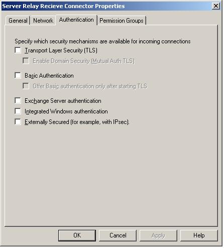
In order to create an SMTP Receive Connector in Exchange 2007 which will allow anonymous SMTP servers within your network to connect and relay mail you will need to complete the following configuration steps.

First, create you Receive Connector as follows, ensuring the ‘Anonymous users’ option is selected inn the ‘Permissions groups’ tab.

The ‘Network’ configuration of this connector limits access to a partiicular server thus preventing unauthorised relay of email:

Finally, the most important stage of this configuration, execute the following shell command using the Exchange Management Sell (EMS), replacing ‘HT_Server_Name’ with the machine name of the Hub Transport Server you configured the new recieve connetcor on:

Normal 0 false false false EN-GB X-NONE X-NONE MicrosoftInternetExplorer4 /* Style Definitions */ table.MsoNormalTable {mso-style-name:”Table Normal”; mso-tstyle-rowband-size:0; mso-tstyle-colband-size:0; mso-style-noshow:yes; mso-style-priority:99; mso-style-qformat:yes; mso-style-parent:””; mso-padding-alt:0cm 5.4pt 0cm 5.4pt; mso-para-margin:0cm; mso-para-margin-bottom:.0001pt; mso-pagination:widow-orphan; font-size:11.0pt; font-family:”Calibri”,”sans-serif”; mso-ascii-font-family:Calibri; mso-ascii-theme-font:minor-latin; mso-fareast-font-family:”Times New Roman”; mso-fareast-theme-font:minor-fareast; mso-hansi-font-family:Calibri; mso-hansi-theme-font:minor-latin; mso-bidi-font-family:”Times New Roman”; mso-bidi-theme-font:minor-bidi;}

Get-ReceiveConnector “HT_Server_Name\Server Relay Receive Connector” | Add-ADPermission -User “NT AUTHORITY\ANONYMOUS LOGON” -ExtendedRights “ms-Exch-SMTP-Accept-Any-Recipient”


Categories
Windows Server 2003

Group Policy Disable Removable Storage Access

Nowadays all security audits will raise the issue of removable storage access. Are you restricting access to Floppy, LS120, CDROM and USB removable storage media? If the answer is no then the ADM file which is availble form this article will help you to resolve that.

Download the adm file here.

Simply add this ADM file to the computer administrative templatesto be able to restrict access to USB drives, CDROM, Floppy and LS-120 drives.

CLASS MACHINE
CATEGORY !!category
 CATEGORY !!categoryname
  POLICY !!policynameusb
   KEYNAME “SYSTEM\CurrentControlSet\Services\USBSTOR”
   EXPLAIN !!explaintextusb
     PART !!labeltextusb DROPDOWNLIST REQUIRED
 
       VALUENAME “Start”
       ITEMLIST
        NAME !!Disabled VALUE NUMERIC 3 DEFAULT
        NAME !!Enabled VALUE NUMERIC 4
       END ITEMLIST
     END PART
   END POLICY
  POLICY !!policynamecd
   KEYNAME “SYSTEM\CurrentControlSet\Services\Cdrom”
   EXPLAIN !!explaintextcd
     PART !!labeltextcd DROPDOWNLIST REQUIRED
 
       VALUENAME “Start”
       ITEMLIST
        NAME !!Disabled VALUE NUMERIC 1 DEFAULT
        NAME !!Enabled VALUE NUMERIC 4
       END ITEMLIST
     END PART
   END POLICY
  POLICY !!policynameflpy
   KEYNAME “SYSTEM\CurrentControlSet\Services\Flpydisk”
   EXPLAIN !!explaintextflpy
     PART !!labeltextflpy DROPDOWNLIST REQUIRED
 
       VALUENAME “Start”
       ITEMLIST
        NAME !!Disabled VALUE NUMERIC 3 DEFAULT
        NAME !!Enabled VALUE NUMERIC 4
       END ITEMLIST
     END PART
   END POLICY
  POLICY !!policynamels120
   KEYNAME “SYSTEM\CurrentControlSet\Services\Sfloppy”
   EXPLAIN !!explaintextls120
     PART !!labeltextls120 DROPDOWNLIST REQUIRED
 
       VALUENAME “Start”
       ITEMLIST
        NAME !!Disabled VALUE NUMERIC 3 DEFAULT
        NAME !!Enabled VALUE NUMERIC 4
       END ITEMLIST
     END PART
   END POLICY
 END CATEGORY
END CATEGORY
 
[strings]
category=”Custom Policy Settings”
categoryname=”Restrict Drives”
policynameusb=”Disable USB”
policynamecd=”Disable CD-ROM”
policynameflpy=”Disable Floppy”
policynamels120=”Disable High Capacity Floppy”
explaintextusb=”Disables the computers USB ports by disabling the usbstor.sys driver”
explaintextcd=”Disables the computers CD-ROM Drive by disabling the cdrom.sys driver”
explaintextflpy=”Disables the computers Floppy Drive by disabling the flpydisk.sys driver”
explaintextls120=”Disables the computers High Capacity Floppy Drive by disabling the sfloppy.sys driver”
labeltextusb=”Disable USB Ports”
labeltextcd=”Disable CD-ROM Drive”
labeltextflpy=”Disable Floppy Drive”
labeltextls120=”Disable High Capacity Floppy Drive”
Enabled=”Enabled”
Disabled=”Disabled”